What is Christie Pandoras Box?
Pandoras Box® is a series of award-winning ProAV media server and multimedia show control software and hardware tools for projection mapping, real-time image compositing, and interactive applications. Pandoras Box is designed to integrate seamlessly with Christie® products, as well as third-party hardware.
Where are ProAV media server and show control solutions used?
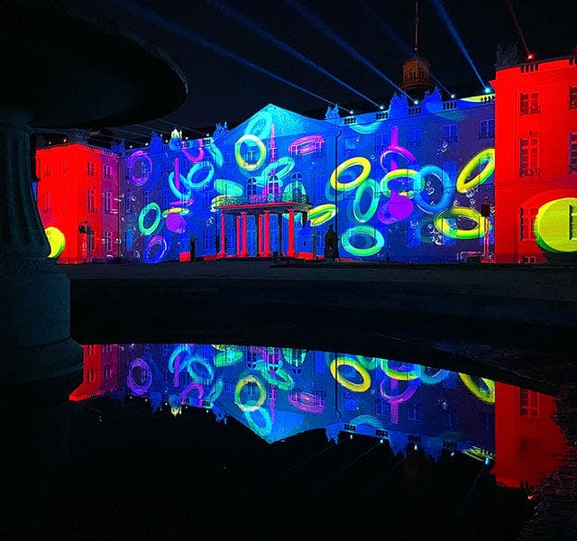
Media server and show control solutions, along with real-time image compositing, are essential for live events, interactive installations and exhibits, projection mapping installations, and any other application that requires the coordination of lighting, sound, imagery, and visual effects.
Media servers are also used in ProAV solutions for museums, broadcast, theme parks, digital signage, dome projection, sporting events, and more.
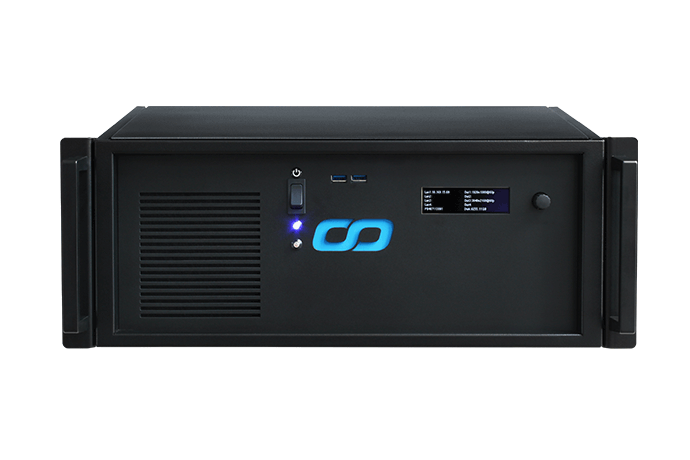
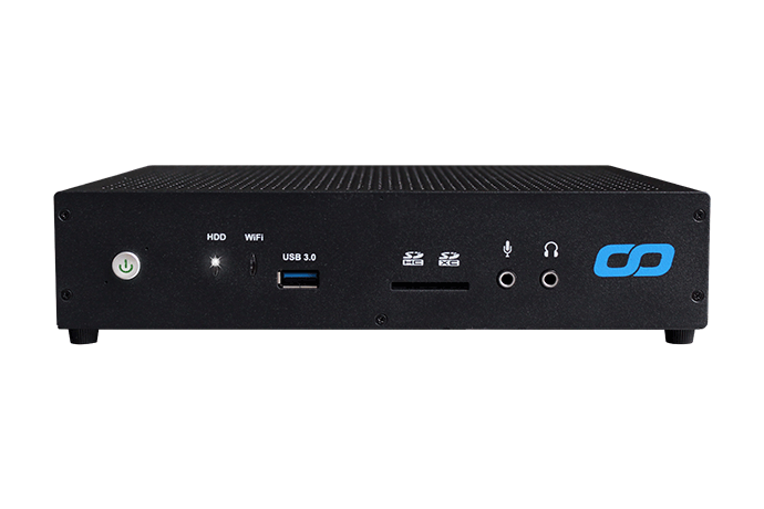
What is a ProAV media server?
Media servers are designed specifically for ProAV setups. They are equipped with high-speed storage technologies, high-end audio playback, and render engines for processing uncompressed video content up to and above 4K and 8K resolutions.
What is show control solution and how will it enhance my project?
Show control solutions are hardware and software tools for coordinating and synchronizing multimedia elements of an installation, such as lighting, sound, video, and special effects. The result is a more immersive and impactful experience for your audience.
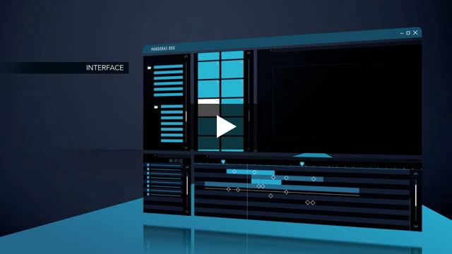
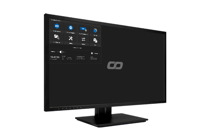
What does media server software do?
Media server software is a specialized application that enables the management and synchronization of multiple audiovisual elements in your ProAV project. The software gives you a centralized interface to control and automate lighting cues, sound cues, video playback, and other effects, ensuring accurate timeline editing and seamless transitions between the different elements. Mapping, real-time show control, and processing are possible in a true 3D or 2D workspace.
What are the key features to look for in a media server software?
Media server or show control software can be highly specialized and choosing the correct one depends on your project’s requirements. Common requirements for this software include synchronized playback, multi-user timeline control, uncompressed playback up to and beyond 8K, 10-bit color depth, real-time tracking, 2D and 3D mapping, and mixed-screen setups. Christie Pandoras Box® Software meets these requirements and more in a complete, flexible solution that reduces setup time and adjusts to any project.
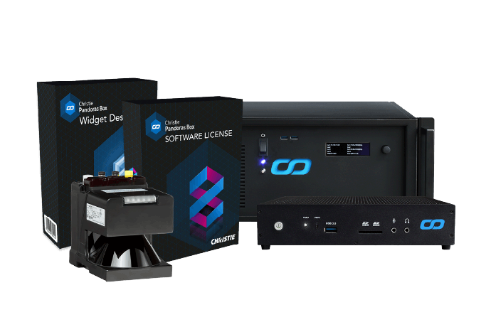
What is Widget Designer?
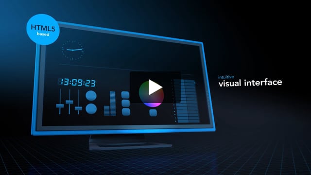
Christie® Widget Designer is a node-based show control creation framework that lets you create dedicated HTML5 user interfaces and interaction logic. Its intuitive interface and simple scripting give even non-programmers the power to create truly immersive interactive experiences. Widget Designer is designed to communicate seamlessly with Pandoras Box® Software and any third-party device.
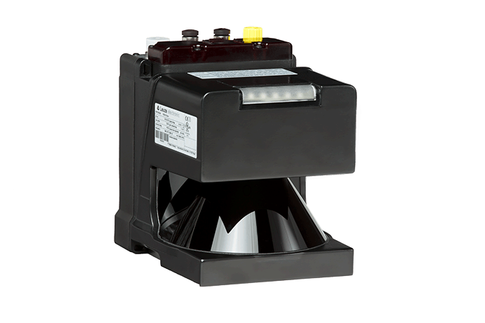
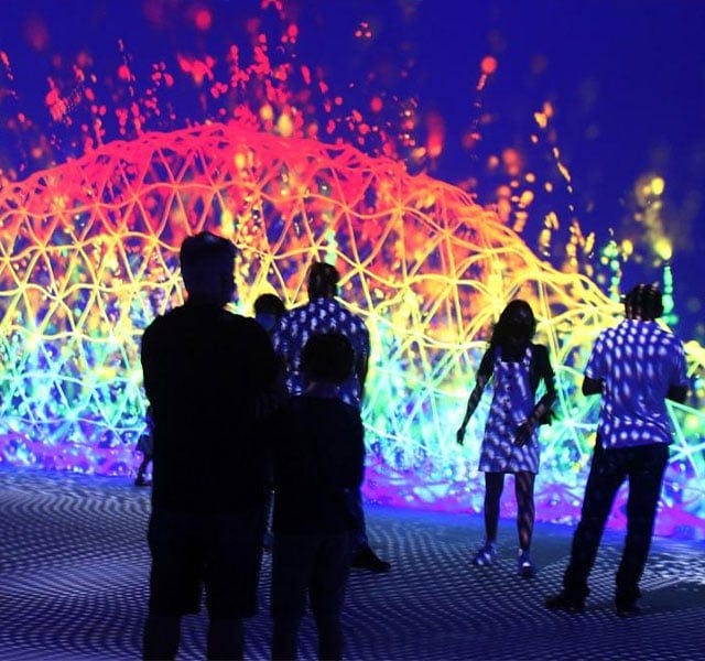
What is AirScan - touchless control
Christie® AirScan is a laser scanner device that measures distances in two dimensions, allowing for optical and contactless detection of objects, people, or their hands. It can be used for any touchless interaction with a display or a projected touch surface. When combined with Widget Designer®, you can quickly customize interactive displays. AirScan is often used for interactive attractions in museum exhibits, game shows, and theme park experiences.